Click here to register for summer batches of robotics. Click here for details of courses.

- Introduction to Electronic Oscillators
- How Tank or Resonant Circuit Works?
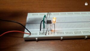
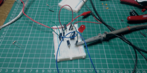
- How RC Phase Shift Oscillator works? Complete working with circuit
- How Wien Bridge Oscillator works? Complete working with circuit
- How Colpitt’s Oscillator circuit works?
- How Hartley Oscillator Circuit works?
Basic Principle: The RC Phase shift oscillator uses common emitter configuration i.e. CE configuration of transistor. It produces 180° phase shift in addition to the phase shift of 180° by the transistor. So we get total 360° phase shift to produce positive feedback.

Working: When supply is connected to the circuit, the base current of T1 suddenly increases. This change is amplified by T1 to produce negative feedback of 180° to the phase shift network.
The phase shift network also produces another 180° phase shift. So the total phase shift is 360° i.e. the input and output signals are in-phase.
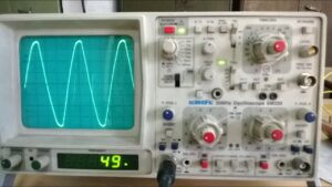
Since transistor T1 is used as amplifier, the circuit produces sustained oscillations. The output frequency of the circuit is given by the following formula:

Where,
R = resistor in phase shift network in ohms
C = capacitor in phase shift network in Farad
Advantages & Disadvantages
- It is a simple circuit using RC network.
- Very low frequency from 1Hz to 300 kHz can be obtained.
- It can be fabricated in integrated circuit form.
- Frequency stability is excellent.
- However, we cannot control frequency easily.
- This circuit is not suitable to produce high frequencies in radio frequency range.