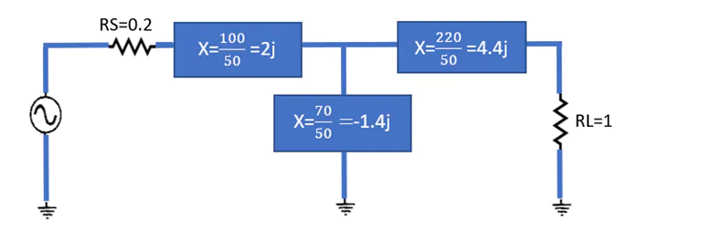
This network is called T because its configuration resembles the Latin letter T. In this configuration, two L-shaped networks with a shared leg are placed adjacently. At the intersection of the two L-shaped networks, a single virtual resistance is considered for this design. The virtual resistor is larger than RL and RS.
If termination impedances are high, (RS,RL)>100 Ω, the Pi network should be implemented. T-shaped networks are applicable if the termination impedances are low, (RS,RL)<100 Ω.
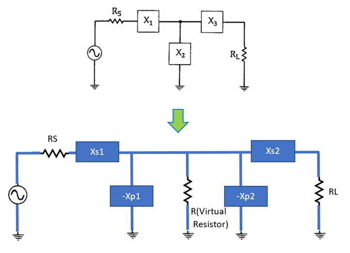
Then the movement between load and source will be divided into two sections ;


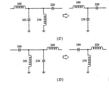
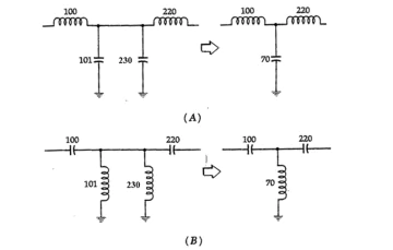
The arrangement of the designed T network can be like each of these below structures:
Applying the values to the smith chart for the first T matching network:


The movement from Zload to Zsource is accomplished with a single L-shaped matching network, as shown below. As the movement from load to source is on impedance circles and upwards, the series inductor is added first. The subsequent movement is on inductance circles and downwards, so the parallel capacitor is added, the Q is 0.7 for this network.
The four-element L-shaped network can be used for the previous example to enhance the bandwidth. Here, the Q is smaller (0.5), allowing for a wider bandwidth. As a result, more series L-shaped matching networks could be considered to increase the bandwidth [2]. The optimum value for Q is achieved by:

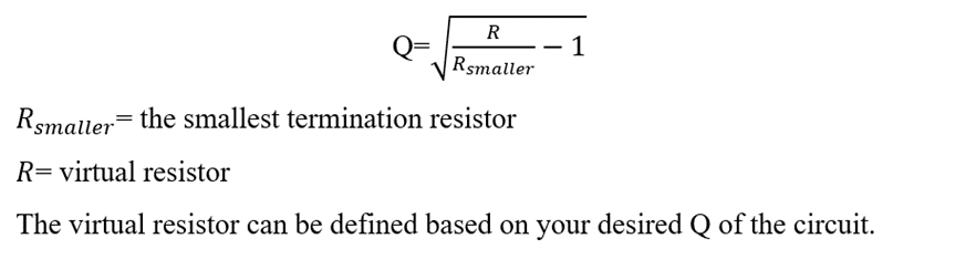
Where R is the virtual resistance ; and RSmaller are RLarger the smallest and largest resistance values. Notably, the Q of each network that operates independently will be higher than when the repetition of networks is considered.


The simplest matching network is the two-element L-shaped one with lowest Q (quality factor) and wide bandwidth. The Q in an L-shaped matching network could not be altered because it is defined by the specific values of the load and source impedances. However, the Pi and T matching networks can be utilized to achieve the desired Q. The Pi network is utilized for high impedances (RS,RL>100Ω) while the T network is utilized for low impedances (RS,RL<100Ω). These two networks have high Q, and are ideal for narrow band matching networks. Notably, a series of L-shaped matching networks can be employed to provide a circuit with wider bandwidth.
Need to understand the matching range of your matching unit?
Click on the link below to see how you can map the matching range of your matching unit quickly and easily.
