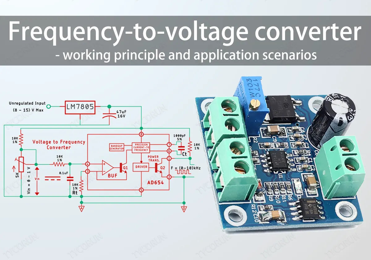
Unlike a 1000w inverter or 3000w inverter that converts DC power into AC power, frequency-to-voltage converter is a device that converts a frequency input signal into its corresponding analog voltage amplitude output signal. The setting of rotation speed is also simple, and is easy to use. So frequency-to-voltage converter is widely used in site operations.
This article will introduce you to what a frequency-to-voltage converter is, its working principle and application scenarios, and list some common frequency-to-voltage conversion circuits.
Main content:
1. What is a frequency-to-voltage converter?
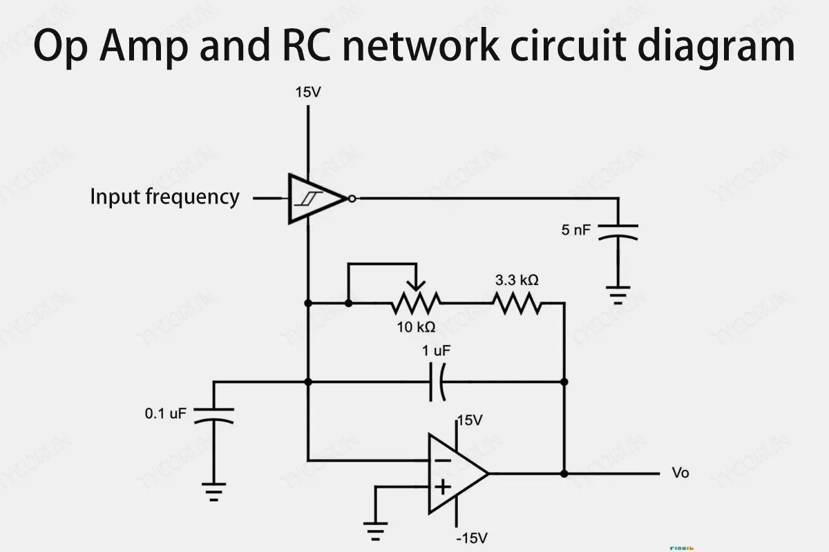
A frequency-to-voltage converter is an electronic device that converts an input frequency signal into a voltage output. The components responsible for frequency conversion of the sinusoidal input include a resistor-capacitor network and an operational amplifier.
The operational amplifier performs the signal processing, while the capacitor network eliminates the ripple frequency or frequency-dependent ripple. In most cases, the input signal frequency range is 0 to 10kHz, while the output is approximately 0 to -10V.
2. Characteristics of frequency-to-voltage converter
- Wide input frequency range 0.1 mHz ~ 100 kHz (DC input)
- Wide voltage range 0.14 ~ 30 Vp-p (AC input)
- The measurement range and output voltage can be set arbitrarily
- With 3-digit simple monitor
- By setting the coefficient, the display of speed can be set
- Small in size and can be connected freely
- DC power supply operating voltage is 10 ~ 42 VDC
3. Application scenarios of frequency-to-voltage converter
A frequency-to-voltage converter is an instrument that converts frequency into a linear output DC current, voltage and isolated analog signal. It can accurately measure the frequency of low-frequency, power frequency, and high-frequency signals. It is an input component for necessary analog quantity acquisition in home solar power system, remote control devices, automated control systems, etc.
The applications of frequency-to-voltage converter circuit include:
- Frequency-to-voltage converter in digital tachometer
- Frequency difference measurement
- Vibration-based touch switch sensor
- Vehicle engine measuring instruments
- Speed controller and governor
- Door lock control
- Horn, clutch and cruise control
4. Working principle of frequency-to-voltage converter
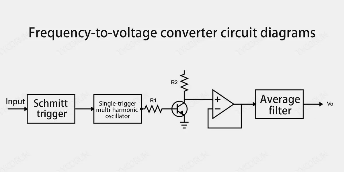
After the capacitor is charged to a certain level, it discharges into the connected integrator or low-pass circuit. This charging and discharging process occurs at all frequency cycles of the input signal. Single-shot multivibrators and precision switches produce frequency pulses up to a specific amplitude and period, which enter an averaging network. After that, the output of the filter is a DC voltage, completing the conversion.
When the charge pump converts the frequency input from the input stage into a DC voltage, an external timing capacitor C1, an output resistor R1 and an integrating capacitor or filter capacitor C2 are required. When the state of the first stage output changes (this may happen when there is a suitable zero-crossing voltage or differential input voltage at the input terminal), the timing capacitor is charged or discharged linearly between the two voltage values with a voltage difference of Vcc/2.
During the half cycle of the input frequency signal, the change in charge on the capacitor is C1Vcc/2, and the average current pumped into the capacitor or out of the capacitor is:
△Q/T=ic(AVG)=fIN C1 VCC
The output circuit accurately sends this current to the load resistor (output resistor) R1, and the other end of the R1 resistor is connected to ground. In this way, the filtered current is integrated by the filter capacitor to obtain the output voltage:
Vo=Vcc fIN C1R1 K
Among them, K is the gain constant, with a typical value of 1. The value of capacitor C2 depends on the size of the ripple voltage and the response time required in the actual application.
For comparison, you can also check the working principle of inverter.
5. Common frequency-to-voltage converter circuits
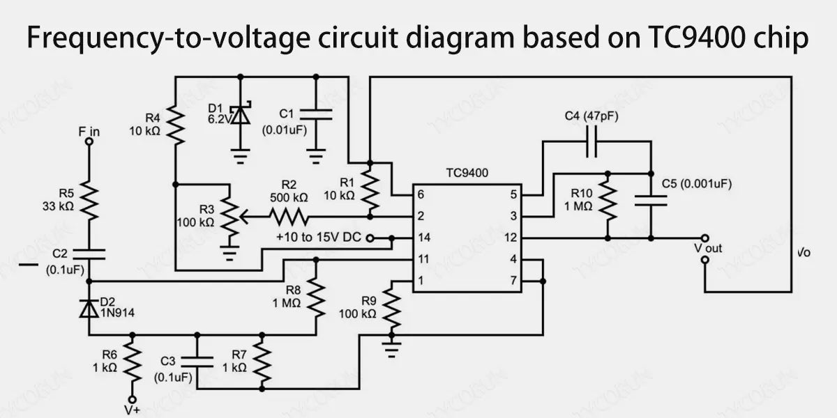
① Frequency-to-voltage converter circuit based on TC9400 chip
You can connect TC9400 IC in frequency-to-voltage converter circuit and vice versa. To make a converter, you need the following components:
- 9 resistors
- 1 trimmer potentiometer
- 2 diodes
- 5 capacitors
The chip takes care of the rest as it contains the following functional blocks:
- One-touch circuit
- Charge and discharge control unit
- Integral operational amplifier
- 3uS delay circuit
- All necessary drivers
Working principle
Conversion begins at pin 11 (the non-inverting input of the internal comparator) where the signal input frequency flows. The minimum frequency to trigger the comparator should be +/-200mV, any sine wave frequency below this will have no effect. Once the frequency wave becomes negative, the internal comparator switches to low level.
When the electric level is low, the 3uS delay circuit activates the C4 charge/discharge circuit, connecting it to the reference voltage. At the same time, the integrating capacitor C5 is also charged to a specific amount of voltage. When this supply voltage operation occurs, a reference voltage is developed between pins 2 and 7.
On the other hand, when the frequency signal wave crosses the positive side, the output of the internal comparator becomes high. This high output disables the C4 charge/discharge network, causing the C4 lead to short circuit. However, the voltage across C5 is preserved because the only available discharge path (R10) has a very high resistance (1M).
Therefore, the voltage stored in C5 becomes the output voltage, while R9 sets the bias current in the chip. The voltage divider network consists of R6 and R7, which is responsible for ensuring that the threshold of the input signal always tracks the supply voltage.
Diode D2 is the main component in the clamp circuit and prevents the input frequency signal from going too far negative to turn on the comparator. Therefore, it acts as a level shifter. You can calibrate the circuit by adjusting potentiometer R3 to get an output of 0V when there is no input signal.
② Frequency-to-voltage converter circuit based on LM331
The LM331 is a high-precision frequency-to-voltage converter that can also be used as a voltage-to-frequency converter. It provides excellent linearity and wide dynamic range, ideal properties for a variety of applications. The circuit is very simple as you only need the following components:
- 6 resistors
- 1 trimmer potentiometer
- 3 capacitors
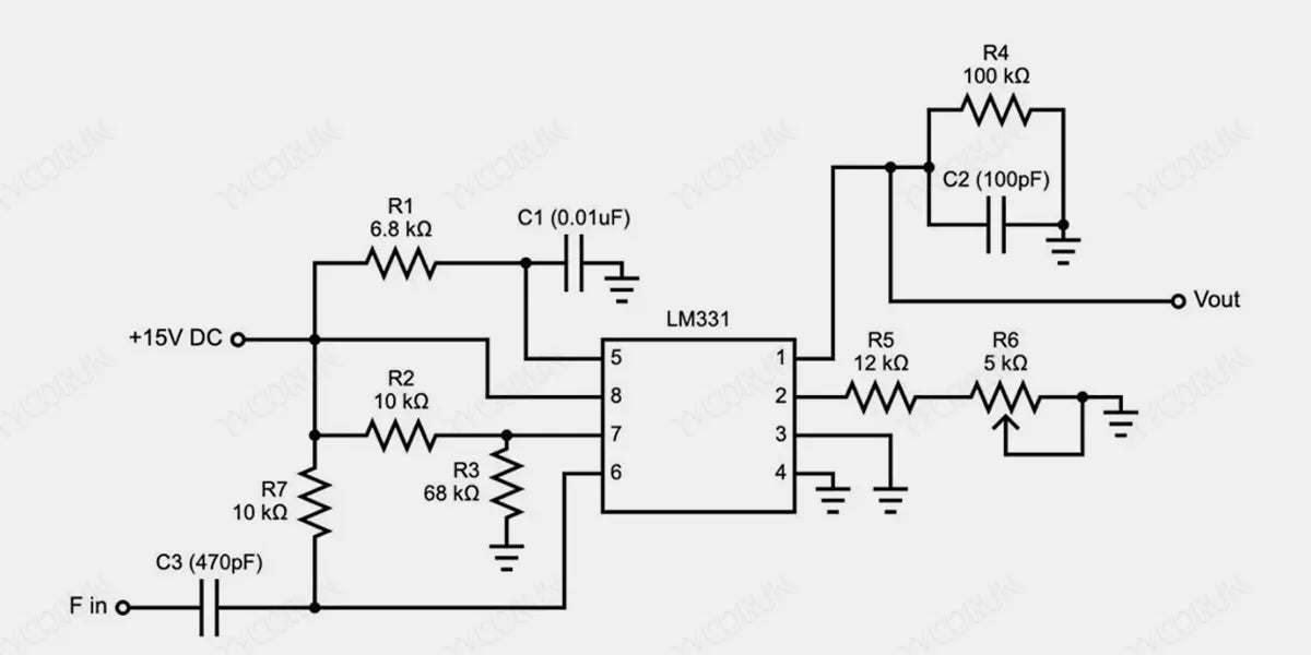
③ Frequency-to-voltage converter based on LM331 IC
The conversion first differentiates the input frequency using C3 and R7, th en feeds the pulse into the chip via pin 6. During the negative period of the frequency sine wave, the built-in comparator activates the timer circuit (R1 and C1). At any time, the current flowing out of the IC is always proportional to the input signal and the timing circuit value. Likewise, the output voltage will be proportional to the frequency signal from R4 (load resistor).
④ Frequency-to-voltage converter circuit configured with VFC32
When using the VFC32 configuration, the 500pF capacitor and the 12K and 2.2K resistors form the capacitive network for the input signal. These components make the comparator inputs compatible with 5V logic flip-flops. The comparator then switches to the associated one-shot stage on each falling edge of the input frequency wave.
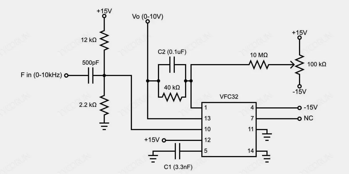
⑤ Frequency-to-voltage converter based on VFC32 IC
In this circuit, the reference threshold input set to the comparator is approximately -0.7V. Therefore, if the input signal is below 5V, the voltage divider network can be adjusted accordingly. Capacitor C2 is responsible for smoothing and filtering the output voltage waveform. Larger C2 values provide better control of the voltage ripple in the output, although the response to changing input frequency signals may be slow.
On the other hand, low C2 values result in poor ripple filtering but fast response to rapidly changing frequencies. The power conversion system operates using charge and balance theory, using an output ramp to trigger a one-shot phase before changing direction.
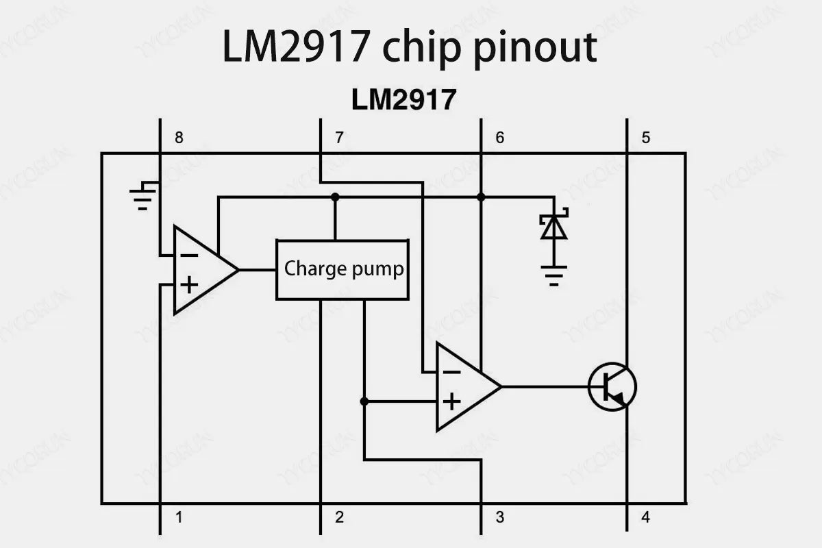
⑥ Frequency-to-voltage converter based on LM2917 IC
The LM2907 and LM2917 are similar in many ways, and their electrical specifications include the following points:
- Can double the low ripple frequency.
- Tachometer input has built-in hysteresis.
- The ground-referenced tachometer pin is directly compatible with all magnetic sensors with different reluctances.
- Ground-referenced tachometer is not affected by input signal frequency changes above the chip supply voltage or -ve potential below zero.
- The output pin connected to the internal common collector transistor can sink up to 50mA. Therefore, it can operate a solenoid directly, be integrated with an output, or act as a CMOS input. With this in mind, the internal structure and pin diagram of the IC are as follows:
The maximum ratings of this chip are:
- 28V power supply voltage
- 25mA power supply current
- 28V internal transistor collector voltage
- 28V differential tachometer input voltage
- +/-28V input voltage range
- 1200-1500mW power consumption
- Other parameters include a current sink output of 40-50mA and a voltage gain of 200V/mV.
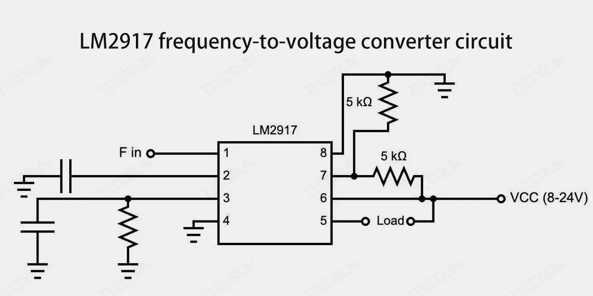
A typical circuit diagram of the converter is shown below:
Related posts: Top 10 power conversion system companies, global top 10 best solar inverter brands, top 10 solar inverters in Australia